VLAN vs Subnetting: Why They Work Better Together
 Tech Guru
Quick Answer
A VLAN separates Ethernet forwarding and broadcast domains; an IP subnet defines an addressing and routing boundary. One subnet per VLAN is a useful simple design, not a protocol law. Align port and SSID membership, trunks, gateway, DHCP or IPv6 services, and explicit firewall policy. Export configurations and keep console or a known-good recovery port before changing the management path.
This workflow assumes a managed switch, a router or firewall, control of the relevant access points, and a written address plan. Confirm local console or out-of-band access before changing the network used for administration.
Start Here: The Beginner Foundation
A VLAN is a logical bridged-LAN construct. Switch ports and links are associated with VLANs so frames in one VLAN normally remain in that Layer 2 forwarding and broadcast domain unless a Layer 3 device routes them elsewhere. IEEE 802.1Q defines VLAN-aware bridging and tagging used to identify VLAN context across shared links. A VLAN ID is locally significant to the bridged design; naming two VLANs the same on separate systems does not automatically connect them.
A subnet is an IP prefix that tells hosts and routers which addresses belong to the same network and how specific routes should match destinations. In IPv4, a prefix such as 192.0.2.0/24 describes the network portion and address set; in IPv6, prefix planning performs the same Layer 3 role with a much larger address space. Hosts use their prefix information to decide whether to communicate on-link or send traffic to a router.
Most straightforward enterprise, home-lab, and small-office designs assign one IP subnet to one VLAN and provide a gateway interface plus DHCP scope for that pair. This is a design convention, not a law of either technology: multiple IP prefixes can exist on one VLAN, and complex bridging can extend a VLAN. However, stretching one subnet across unrelated VLANs or placing the same subnet on multiple routed interfaces creates ambiguity. Real isolation also requires deliberate inter-VLAN routing and firewall policy.
The Fast Comparison
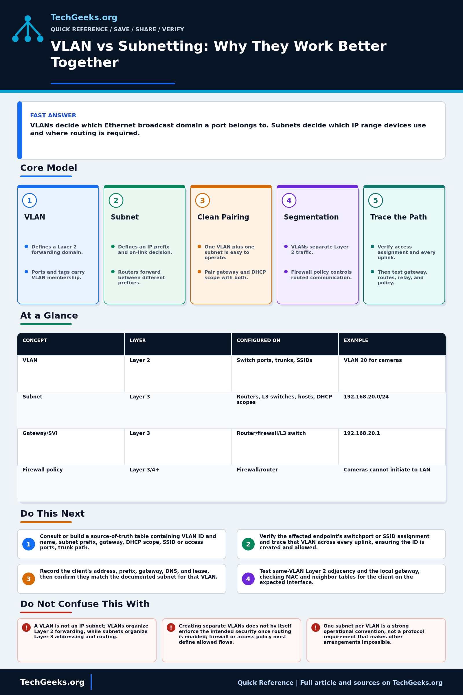
| Concept | Layer | Configured on | Example |
|---|---|---|---|
| VLAN | Layer 2 | Switch ports, trunks, SSIDs | VLAN 20 for cameras |
| Subnet | Layer 3 | Routers, L3 switches, hosts, DHCP scopes | 192.168.20.0/24 |
| Gateway/SVI | Layer 3 | Router/firewall/L3 switch | 192.168.20.1 |
| Firewall policy | Layer 3/4+ | Firewall/router | Cameras cannot initiate to LAN |
Advanced Notes and Design Boundaries
The operational unit is the VLAN-to-prefix mapping and its entire path: access port or SSID, every trunk, gateway interface, DHCP or router-advertisement service, connected route, return route, and firewall policy. A VLAN ID or subnet written in isolation is not a deployable segmentation design.
- The 802.1Q tag carries a 12-bit VLAN identifier field; values 1 through 4094 are available for ordinary VLAN identification, while 0 and 4095 have reserved meanings.
- A port VLAN identifier, or PVID, classifies suitable untagged ingress frames into a VLAN; tagging on egress and accepted VLAN membership are separate per-port decisions.
- A switched virtual interface, routed VLAN interface, or router subinterface supplies Layer 3 adjacency for a VLAN, but its existence does not by itself define permissive inter-VLAN firewall policy.
- DHCPv4 broadcasts do not normally cross the routing boundary between VLAN subnets, so each subnet needs a local server or correctly configured relay and matching scope.
- IPv6 SLAAC conventionally uses a /64 per LAN, and router advertisements plus neighbor discovery must be planned per link; copying an IPv4 subnet plan mechanically into IPv6 can break expected host behavior.
Troubleshooting Workflow
Trace one affected endpoint end to end before changing the design. Keep a console or known-good untagged recovery port available, save each device configuration, and change access, trunk, gateway, DHCP, and policy elements in a sequence that does not strand management.
- Consult or build a maintained network table containing VLAN ID and name, subnet prefix, gateway, DHCP scope, SSID or access ports, trunk path, and allowed flows.
- Verify the affected endpoint's switchport or SSID assignment and trace that VLAN across every uplink, ensuring the ID is created and allowed end to end.
- Record the client's address, prefix, gateway, DNS, and lease, then confirm they match the documented subnet for that VLAN.
- Test same-VLAN Layer 2 adjacency and the local gateway, checking MAC and neighbor tables for the client on the expected interface.
- Inspect the gateway interface, connected route, DHCP relay, and return route before evaluating inter-VLAN or upstream firewall policy.
- Test one explicitly allowed and one explicitly denied flow, then review firewall logs to prove the segmentation policy rather than inferring it from VLAN presence.
Evidence and Segmentation Acceptance Tests
The concepts and limits here are documentation-backed; TechGeeks did not deploy this design across a representative multi-vendor lab. Validate every intended endpoint class and path with saved configuration, forwarding state, address leases, routes, and policy logs.
- For each VLAN, connect a test endpoint to every relevant access-port and SSID type. Confirm its MAC or client identity appears in the intended VLAN and it receives the documented IPv4 or IPv6 prefix, gateway, and DNS service.
- Verify the VLAN is present and allowed across each trunk, with intentional native or untagged behavior and no mismatch. Check both ends rather than relying on one controller view.
- Test same-VLAN reachability and the local gateway, then inspect MAC, ARP, and IPv6 neighbor state on the expected interfaces.
- Test at least one permitted and one prohibited inter-VLAN flow in both initiation directions. Match results to the intended firewall rule and logs.
- Test required DNS, DHCP relay, IPv6 router advertisements, NTP, printing, casting, or discovery helpers without opening broader access than the application needs.
- Export the accepted configuration and record a rollback sequence. Prove that console or the recovery port remains reachable before removing the former management address or VLAN.
Security, Privacy, and Recovery Boundaries
- VLAN tags separate Layer 2 forwarding domains; they do not encrypt traffic or authorize routed flows. Enforce least-privilege policy at the gateway and protect switch, AP, and firewall management separately.
- Do not expose device administration on an untrusted user or IoT VLAN. Restrict management protocols, rotate default credentials, and retain an emergency access method outside the changed path.
- Packet captures, DHCP logs, ARP tables, and controller exports can identify users, devices, addresses, and destinations. Capture only what is necessary and redact evidence before sharing it.
- Discovery gateways and reflectors deliberately relay selected traffic across boundaries. Scope services and destinations narrowly, log their behavior, and reassess them after device updates.
- Schedule changes that affect trunks, native VLANs, gateways, or DHCP with a tested rollback sequence. Restore the previous configs in dependency order when management is lost or acceptance flows diverge from policy.
What This Does Not Mean
- Separate VLAN IDs do not prove security isolation once a router or Layer 3 switch can forward between them; tested policy provides that evidence.
- A client receiving the expected IP address does not prove its frames carried the intended tag across every trunk or that all return paths are correct.
- A successful ping proves only that particular control exchange at that moment; it does not prove application ports, initiation direction, DNS, discovery, capacity, or denial rules.
- Matching VLAN names or numbers on two devices do not establish connectivity; port membership, tags, native behavior, and the whole link path must agree.
- One subnet per VLAN is a strong operational convention, not a protocol law, and exceptions require explicit neighbor, DHCP, routing, and failure analysis.
Real-World Use Cases
- Map every VLAN to a subnet in your documentation.
- Create a DHCP scope for each user/device subnet.
- Use firewall policy for segmentation rules.
- Use access ports for endpoints and trunks between network devices.
Failure Patterns to Recognize
- Clients get the wrong DHCP scope because a port is in the wrong VLAN.
- Inter-VLAN routing is missing or blocked.
- Native VLAN mismatch causes strange traffic leaks.
- DNS/mDNS discovery breaks across subnets without helpers or policy.
Common Mistakes
- Creating VLANs without firewall rules and calling it secure.
- Using one subnet across multiple VLANs without a specific design reason.
- Leaving management interfaces reachable by untrusted clients and assuming a different VLAN number alone fixes it.
- Forgetting DHCP relay for routed VLANs.
Quick Checklist
- List VLAN ID, name, subnet, gateway, DHCP scope, and allowed flows.
- Check access/trunk port config.
- Verify client IP matches expected VLAN.
- Test gateway and DNS.
- Review firewall rules before adding devices.
Common Questions
Useful Gear And Buyer Notes
Affiliate disclosure: As an Amazon Associate, TechGeeks may earn from qualifying purchases. The product links below are buying references, not a requirement to buy a specific brand or seller. Verify compatibility, seller quality, warranty, and current specs before ordering.
Select a managed switch and gateway only after listing VLAN count, port roles, trunk and LAG needs, PoE demand, inter-VLAN throughput, IPv6, DHCP relay, policy, logs, and support lifetime. A label maker helps operations, but labels must match the saved network records and configuration rather than become the only documentation.
Related TechGeeks Reading
- A Beginner VLAN Layout for a Homelab
- Homelab VLAN Design and Network Segmentation
- IoT Isolation with Homelab VLANs, Firewall Rules, and mDNS
References
- IEEE SA: IEEE 802.1Q-2022, Bridges and Bridged Networks
- RFC 1918: Address Allocation for Private Internets
- RFC Editor: RFC 4632, Classless Inter-domain Routing
- RFC Editor: RFC 1812, Requirements for IP Version 4 Routers
- RFC Editor: RFC 4862, IPv6 Stateless Address Autoconfiguration
- Juniper: Bridging and VLANs
- TechTarget: independent comparison of VLANs and subnets