SFP, SFP+, SFP28, QSFP, and QSFP-DD Explained
 Tech Guru
Quick Answer
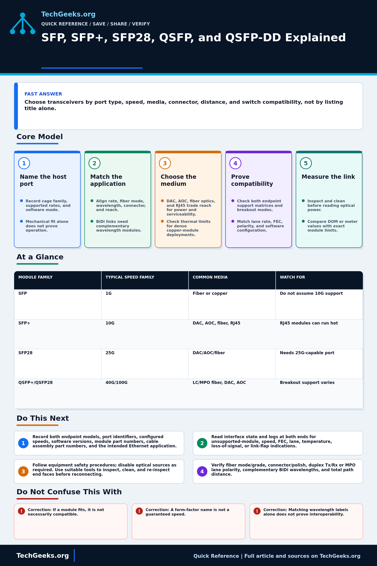
Choose a transceiver from the exact host port's compatibility matrix, not its cage shape. Match both endpoint models and software, Ethernet rate, media, connector, wavelength, strand or lane count, reach, and power/cooling limits. Check receive overload as well as sensitivity. Keep a known-good supported module and cable for rollback, and follow optical safety procedures before inspecting or swapping a live link.
Start Here: The Beginner Foundation
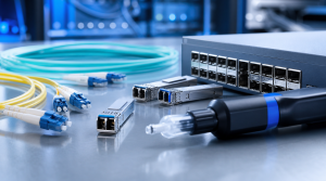
A pluggable transceiver is the removable interface between a network port and its cable. Names such as SFP, SFP+, SFP28, QSFP28, and QSFP-DD mainly describe module and host-interface families; they do not, by themselves, prove a particular Ethernet speed, reach, wavelength, or connector. Start with the exact switch or network-adapter port, its supported speeds, and its compatibility documentation before selecting the module.
After the host port is known, match the complete optical or electrical application. That includes the rate and protocol, fiber mode, wavelength or wavelength pair, connector, number of fibers or lanes, and required reach. For example, a common 10GBASE-SR SFP+ uses multimode fiber and duplex LC, while a 10GBASE-LR SFP+ uses single-mode fiber and duplex LC; a bidirectional optic may use one fiber but requires a complementary transmit and receive wavelength at the far end.
The cable choice is part of the link design. A passive or active direct-attach copper cable, an active optical cable, a replaceable optical module with patch cords, and an RJ45 module have different reach, power, cooling, serviceability, and compatibility characteristics. Bring the link up only after checking both ends, cleaning optical interfaces, and comparing measured transmit and receive power with the limits for the exact module rather than with a generic number.
The Fast Comparison
| Module family | Typical speed family | Common media | Watch for |
|---|---|---|---|
| SFP | 1G | Fiber or copper | Do not assume 10G support |
| SFP+ | 10G | DAC, AOC, fiber, RJ45 | RJ45 modules can run hot |
| SFP28 | 25G | DAC/AOC/fiber | Needs 25G-capable port |
| QSFP+/QSFP28 | 40G/100G | LC/MPO fiber, DAC, AOC | Breakout support varies |
| QSFP-DD family | 200G through 1.6T variants | High-density optics | Exact generation, lane rate, thermal limit, and host support must match |
Advanced Notes and Design Boundaries
Check mechanical fit, host electrical lanes, management support, protocol and rate, the optical or copper application, the cable path, firmware support, and cooling at both endpoints. A module that fits the cage can still fail any of those requirements.
- Treat the MSA form factor, host electrical interface, module management interface, and Ethernet optical PMD as separate contracts; a mechanically insertable module can still be unsupported electrically, thermally, in firmware, or at the requested lane rate.
- Typical associations are SFP with 1 GbE, SFP+ with 10 GbE, SFP28 with 25 GbE, QSFP+ with 40 GbE, QSFP28 with 100 GbE, and QSFP-DD-family modules with higher aggregate rates. Exceptions and multi-rate ports exist, so the platform support matrix remains authoritative.
- For an optical budget, compare minimum transmitter output with receiver sensitivity and subtract connector, splice, fiber, splitter, and engineering-margin losses. Also compare maximum transmitter output with receiver overload; a long-reach optic on a very short path can require attenuation when its documentation calls for it.
- Digital optical monitoring (DOM) can expose receive power, transmit power, temperature, supply voltage, and laser bias, but available fields, calibration accuracy, thresholds, and alarm behavior vary. Use DOM as evidence alongside a calibrated power or loss test, not as universal cable certification.
- Breakout operation requires more than the right fanout cable: the host must support the breakout mode, lane mapping, speed combination, forward error correction (FEC), and software configuration. A QSFP-family cage or QSFP-DD cage does not guarantee every lower-rate module, adapter, or breakout mode is enabled.
Troubleshooting Workflow
Treat both endpoints and the entire media path as one system. Record the working state before swapping anything, then substitute one known-compatible module, patch lead, adapter, or port at a time so a coding, polarity, cleanliness, FEC, or optical-budget fault is not masked by simultaneous changes.
- Record both endpoint models, port identifiers, configured speeds, software versions, module part numbers, cable assembly part numbers, and the intended Ethernet application; check each item in the platform compatibility matrix.
- Read interface state and logs at both ends for unsupported-module, speed, FEC, lane, temperature, loss-of-signal, or link-flap indications, then make the administrative and breakout configurations agree.
- De-energize or disable the optical source as required by the equipment procedure, inspect every accessible end face with suitable equipment, clean contaminated interfaces, and re-inspect before reconnecting.
- Verify media end to end: fiber mode and grade, connector and polish, duplex transmit-to-receive polarity or MPO lane polarity, wavelength pairing for BiDi optics, and total path distance.
- Collect DOM from both endpoints and compare actual transmit and receive levels with the exact module's minimum, maximum, sensitivity, and overload specifications; use a calibrated optical power meter or optical loss test set (OLTS) when DOM is missing or inconclusive.
- Substitute one known-compatible component at a time, starting with patch leads and modules, and move a suspected module to a known-good supported port when safe. If the fault remains in the permanent plant, measure end-to-end loss and use an OTDR with appropriate launch and receive cords to locate events.
Evidence and Link Acceptance Tests
This article is documentation-backed; TechGeeks did not qualify every listed form factor, optic, host platform, or breakout mode in a lab. For a real deployment, preserve the exact compatibility entries, interface counters, telemetry, and test duration for each endpoint and software release.
- Confirm that both host ports explicitly support the module, protocol, rate, lane mapping, power class, breakout mode, and required FEC in the installed software.
- Verify the complete application at both ends: wavelength or complementary BiDi pair, fiber mode, connector and polish, strand count, polarity, cable reach, and path-loss budget including an engineering margin.
- Inspect and clean optical end faces, then record transmit and receive power, temperature, voltage, and alarms from both endpoints. Compare values with the exact module specifications, including receiver overload as well as sensitivity.
- Run sustained traffic appropriate to the service and watch symbol, FEC, CRC, discard, flap, and lane counters. Acceptance requires stable forwarding and no unexplained counter growth, not merely an up state.
- Exercise every intended breakout lane or failover path and confirm monitoring identifies the correct physical module and lane.
- Reinsert the known-good supported module and cable to prove rollback. Keep that baseline available until the new link has completed its observation period.
Laser Safety, Support, and Recovery Boundaries
- Never look into a fiber, connector, or module aperture. Treat it as active until verified otherwise, follow the equipment's laser-safety procedure, and use suitable inspection and measurement equipment.
- Protect modules from electrostatic discharge, keep dust caps on clean disconnected interfaces, and observe the host's insertion, removal, and hot-swap instructions.
- Third-party coding may operate while changing vendor support or warranty handling. Record the platform policy, qualify the exact hardware and software combination, and keep a vendor-supported spare for fault isolation.
- Dense copper modules and high-rate optics can exceed cage or airflow limits. Check per-port and adjacent-port restrictions rather than assuming that every physically available slot can be populated.
- Inventory and DOM exports can reveal topology, serial numbers, and path design. Limit access to that operational data and redact it before sharing troubleshooting evidence.
- Do not replace several live-link components at once or clean a powered interface contrary to procedure. Restore the known-good path when errors rise, telemetry approaches a limit, or the platform rejects the module.
What This Does Not Mean
- A module fitting the cage does not prove electrical, thermal, firmware, power-class, rate, or management compatibility.
- Matching wavelength labels do not prove interoperability; modulation, lane count, FEC, optical levels, fiber mode, and complementary BiDi direction can still differ.
- DOM values within alarm thresholds do not certify the fiber plant or prove adequate engineering margin; thresholds, calibration, and exposed fields vary.
- Link-up and a short ping do not prove acceptable bit-error performance, stability under load, breakout-lane health, or failover behavior.
- A 1 GbE module working in one SFP-family cage does not prove that the same port or adapter supports 10 or 25 GbE in either direction.
Real-World Use Cases
- Use DAC for short same-rack connections.
- Use SR optics with multimode fiber for short fiber runs.
- Use LR optics with single-mode fiber for longer runs.
- Check DOM/DDM support if monitoring light levels matters.
Failure Patterns to Recognize
- Wrong fiber mode for optic type.
- LC vs MPO connector mismatch.
- Vendor-coded module rejected by switch.
- RJ45 SFP+ overheats in dense ports.
- Breakout cable unsupported.
Common Mistakes
- Buying modules before checking the switch support matrix.
- Mixing single-mode and multimode patch cords.
- Ignoring transmit distance and receive sensitivity.
- Using unknown optics in production without spares.
Quick Checklist
- Check port type and supported speeds.
- Choose media and distance.
- Choose connector.
- Verify vendor compatibility.
- Test link and light levels.
- Keep spares labeled.
Common Questions
Useful Gear And Buyer Notes
Affiliate disclosure: As an Amazon Associate, TechGeeks may earn from qualifying purchases. The product links below are buying references, not a requirement to buy a specific brand or seller. Verify compatibility, seller quality, warranty, and current specs before ordering.
Order against the exact endpoint matrix and application: host coding, speed, FEC, media, connector, wavelength, reach, temperature range, and power class. Include labeled known-good spares and cleaning supplies; a cheaper module that cannot be supported or isolated during an outage can cost more than the link.
- Amazon search: SFP+ DAC cable
- Amazon search: 10G SFP+ SR transceiver
- Amazon search: LC fiber patch cable
Related TechGeeks Reading
- Cisco C9550 Smart Switches and the AI-Ready Campus Core
- The Cisco Catalyst Smart Switch Story: C9350, C9550, and Silicon One
- Networking Field Notes: Start Here
References
- Cisco transceiver modules compatibility information
- IEEE 802.3-2022 Ethernet Standard
- SNIA SFF Technology Affiliate: current specifications
- Cisco: 400G QSFP-DD cable and transceiver modules
- Cisco: transceiver module data sheets and support
- Cisco: 10GBASE SFP+ modules data sheet
- Cisco: 100GBASE QSFP-100G modules data sheet
- Fiber Optics Association: fiber-optic transceivers