Single-Mode vs Multi-Mode Fiber: Which One Should You Run?
 Tech Guru
Quick Answer
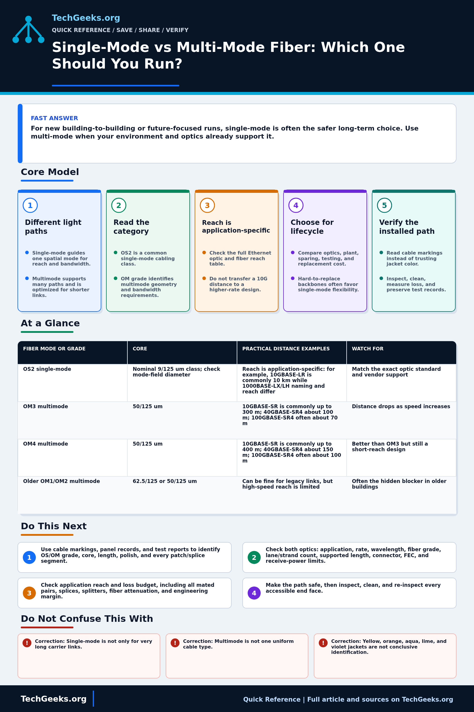
Single-mode is often a practical baseline for new building-to-building or hard-to-replace routes. Multimode can remain suitable when the existing grade, patching, and optics meet the required application and distance. Check the exact transceiver reach table and loss budget, not jacket color. Neither mode is automatically future-proof, and the cable construction still has to suit the route and local installation rules.
Identify the route, required applications, strand count, connectors, environmental listing, and endpoint optics before selecting cable. Building and campus work needs competent design and testing under the applicable local code; never look into an open fiber or transceiver.
Start Here: The Beginner Foundation
Single-mode and multimode fiber guide light differently. Single-mode fiber has a much smaller light-guiding region and is normally paired with laser optics designed for longer reach and high bandwidth over distance. Multimode fiber has a larger core that supports many light paths, making it practical for many short premises and data-center links but subject to modal dispersion that limits reach as applications become more demanding.
The familiar cabling categories are not interchangeable. OS2 identifies a common premises-cabling class for single-mode installations, while OM1 through OM5 identify multimode grades with different core sizes or bandwidth performance; OM3, OM4, and OM5 are laser-optimized 50/125 micrometer fibers. These labels come from cabling and fiber standards, while the transceiver's Ethernet application specifies which category, wavelength, connector arrangement, and maximum channel it supports.
Choose by the installed environment, required rate and reach, upgrade horizon, and total system cost. Single-mode is often attractive for new backbones, building-to-building paths, and routes that are expensive to replace, while multimode can be sensible when a short existing plant, patching system, and optic inventory already use a supported OM grade. Whichever mode is chosen, document the actual cable marking and validate the exact application rather than making the decision from jacket color.
The Fast Comparison
| Fiber mode or grade | Core | Practical distance examples | Watch for |
|---|---|---|---|
| OS2 single-mode | Nominal 9/125 um class; check mode-field diameter | Reach is application-specific: for example, 10GBASE-LR is commonly 10 km while 1000BASE-LX/LH naming and reach differ | Match the exact optic standard and vendor support |
| OM3 multimode | 50/125 um | 10GBASE-SR is commonly up to 300 m; 40GBASE-SR4 about 100 m; 100GBASE-SR4 often about 70 m | Distance drops as speed increases |
| OM4 multimode | 50/125 um | 10GBASE-SR is commonly up to 400 m; 40GBASE-SR4 about 150 m; 100GBASE-SR4 often about 100 m | Better than OM3 but still a short-reach design |
| Older OM1/OM2 multimode | 62.5/125 or 50/125 um | Can be fine for legacy links, but high-speed reach is limited | Often the hidden blocker in older buildings |
| Mixed mode | Application-dependent | Use only when the exact application and vendor documentation support the pairing | Do not infer support from connector fit |
Advanced Notes and Design Boundaries
Write down the current and planned applications, route replacement cost, fiber specifications, connector and splice layout, strand count, optical limits, endpoint optics, spares, and test equipment. Those details determine whether the channel can be supported; the mode label alone does not.
- OM1 is generally 62.5/125 micrometers, while standardized OM2, OM3, OM4, and OM5 are 50/125 micrometers with distinct bandwidth requirements. Substituting one multimode grade for another can change supported reach even when connectors and jacket colors look similar.
- As one application-specific example, Cisco's current 10GBASE-SR data sheet lists up to 300 meters on 2000 MHz-km OM3 and 400 meters on 4700 MHz-km OM4. Those numbers should not be reused for 40, 100, 200, or 400 GbE applications, which have their own lane, fiber-count, and reach definitions.
- OS2, ITU-T G.652.D, and bend-insensitive G.657 labels describe related but different standards contexts. Many products satisfy more than one designation, but an engineer should verify the cable and bare-fiber compliance statements instead of treating the names as exact synonyms.
- Multimode reach is constrained by modal bandwidth and differential mode delay as well as attenuation. Single-mode eliminates multimode modal dispersion, but long or high-rate systems can still be limited by chromatic dispersion, polarization effects, reflections, nonlinear effects, or the optic's power budget.
- Compare lifecycle cost, not an old rule that one mode always has cheaper optics. Module pricing, port density, breakout design, connector count, existing plant, sparing, testing skills, and the cost of replacing a pathway can outweigh the patch-cable price.
Troubleshooting Workflow
Start with records and non-destructive measurements. Preserve the original patching and polarity map, make the optical path safe, then inspect, clean, and test methodically so an emergency patch does not introduce a second mode, polish, or lane-mapping problem.
- Read the cable legend, patch-panel records, and test report to identify OS or OM category, core size, length, connector polish, and every patch or splice segment; do not infer the plant solely from jacket color.
- Identify the exact transceiver application at both ends, including rate, wavelength, required fiber mode and grade, lane or strand count, supported channel length, connector, FEC, and receive-power limits.
- Compare the installed channel with the application's reach table and calculate its loss allowance, including all mated pairs, splices, splitters, attenuation, and engineering margin.
- Make the path safe, then inspect, clean, and re-inspect every accessible end face. Verify that all patch cords preserve the documented mode, grade, polish, and transmit-to-receive or parallel-lane polarity.
- Measure receive power or perform a correctly referenced optical loss test set (OLTS) measurement at the specified wavelength and launch condition; compare results with the application limit and any original acceptance baseline.
- For unexplained excess loss or intermittent behavior, use an optical time-domain reflectometer (OTDR) configured for the correct mode and wavelength with launch and receive cords. Locate mixed-fiber events, bends, bad splices, or reflections, repair them, and repeat the end-to-end test.
Evidence and Fiber Acceptance Tests
This comparison is documentation-backed; TechGeeks did not install, certify, or age a representative OS2, OM3, or OM4 channel for this review. The acceptance package for an actual run should identify every tested strand and retain raw results, limits, instrument settings, and route records.
- Document cable manufacturer and marking, fiber mode and grade, environmental and fire listing, route length, strand IDs, connector type and polish, splices, patch panels, and end-to-end polarity.
- Calculate the loss budget for each intended application at its specified wavelength, including connector, splice, splitter, fiber, and engineering-margin allowances.
- Inspect, clean, and re-inspect accessible end faces. Perform standards-appropriate OLTS testing with the correct references and launch conditions; use OTDR traces with launch and receive cords when event location or reflectance evidence is required.
- Save pass/fail results per strand at required wavelengths and compare them with both the cabling limit and the stricter application budget.
- Install the exact endpoint optics, record receive and transmit power at both ends, run sustained traffic, and watch error and flap counters.
- Deliver updated route, splice, panel, polarity, and labeling records plus baseline traces. Preserve the old path or known-good patching until every intended service and failover path passes.
Safety, Code, and Recovery Boundaries
- Never look into a fiber end or transceiver. Treat the path as energized until verified otherwise and follow laser-safety procedures for inspection, cleaning, and measurement.
- Cable listing, pathway fill, firestopping, building entry, water blocking, bonding of metallic components, and outside-plant protection are site- and jurisdiction-specific. Obtain the required design and permit review.
- Do not mate incompatible connector polishes or mix fiber modes as an improvised repair. Protect clean ends with caps and control shards from cleaving or splicing.
- Route maps and strand assignments expose physical network topology. Restrict them to people who need access and redact sensitive facility details from shared test reports.
- For a migration, label both ends before work, export endpoint configurations, keep known-good optics and patch leads, and define the time or error threshold that triggers restoration of the former path.
What This Does Not Mean
- Jacket color does not prove mode, grade, listing, polarity, or test performance; read the cable marking and acceptance record.
- A passing attenuation result at one wavelength does not prove compliance at another wavelength, correct reflectance, polarity, application reach, or future higher-rate support.
- Single-mode fiber offers broad reach options but is not automatically future-proof; strand count, connector performance, route condition, dispersion, and future optics still matter.
- Multimode working at 10 GbE does not prove the same channel supports 40, 100, or 400 GbE; each application has its own grade, lane, and reach rules.
- Detecting light across mixed modes does not prove a stable or supported channel. Mode-field mismatch can produce excessive or direction-dependent loss.
Real-World Use Cases
- Choose single-mode for outdoor, campus, building-to-building, and hard-to-replace backbone runs.
- Use multimode when existing patch panels and optics require it or when the link is short and the environment already has OM3/OM4 standards.
- Document OM grade if using multimode; aqua cable alone is not enough documentation.
- Check the exact transceiver data sheet for the speed, wavelength, fiber grade, and supported reach before ordering.
- Keep patch cable colors consistent with standards where possible.
Failure Patterns to Recognize
- A 10G SR link fails over a long multimode run.
- Single-mode patch cord is used with multimode plant.
- Old OM1/OM2 cabling limits higher speeds.
- Connector polish mismatch adds loss.
Common Mistakes
- Choosing multimode because it sounds cheaper without checking future optics.
- Assuming all aqua cables are equivalent.
- Ignoring modal bandwidth and distance tables.
- Mixing patch cords during emergency changes.
Quick Checklist
- Record distance.
- Check required speed now and later.
- Check existing fiber grade.
- Compare OS2, OM3, and OM4 reach tables for that speed.
- Match optic type to mode.
- Test link budget.
Common Questions
Useful Gear And Buyer Notes
Affiliate disclosure: As an Amazon Associate, TechGeeks may earn from qualifying purchases. The product links below are buying references, not a requirement to buy a specific brand or seller. Verify compatibility, seller quality, warranty, and current specs before ordering.
Order patch leads only after confirming mode or OM grade, connector body, polish, fiber count, polarity, jacket listing, and the exact optic application. For permanent cabling, the installation, labels, test results, and warranty are part of the deliverable; low cable price does not compensate for an undocumented path.
Related TechGeeks Reading
- Campus Segmentation Design: From VLANs to Unified Fabric
- Cisco C9550 Smart Switches and the AI-Ready Campus Core
- Networking Field Notes: Start Here
References
- Fiber Optics Association: fiber types
- Fiber Optics Association: installation documentation and test deliverables
- ITU-T G.652 (08/2024): characteristics of single-mode optical fiber and cable
- IEC 60793-2-10:2019+A1:2022: category A1 multimode fibers
- ISO/IEC 11801-1:2017 with current amendments: generic cabling requirements
- Cisco: 10GBASE SFP+ modules and application-specific fiber reaches