Fiber Optic Cables Explained: Structure, Distance, and Use Cases
 Tech Guru
Quick Answer
Choose fiber as part of a complete link: match the optic, fiber mode and grade, reach, connectors, polish, and pathway-rated cable. Include connector and splice losses in the optical budget, then inspect and measure the installed path. Never look into an open fiber or optical port. A link light alone does not prove safe installation, adequate margin, or reliable service.
Start Here: The Beginner Foundation
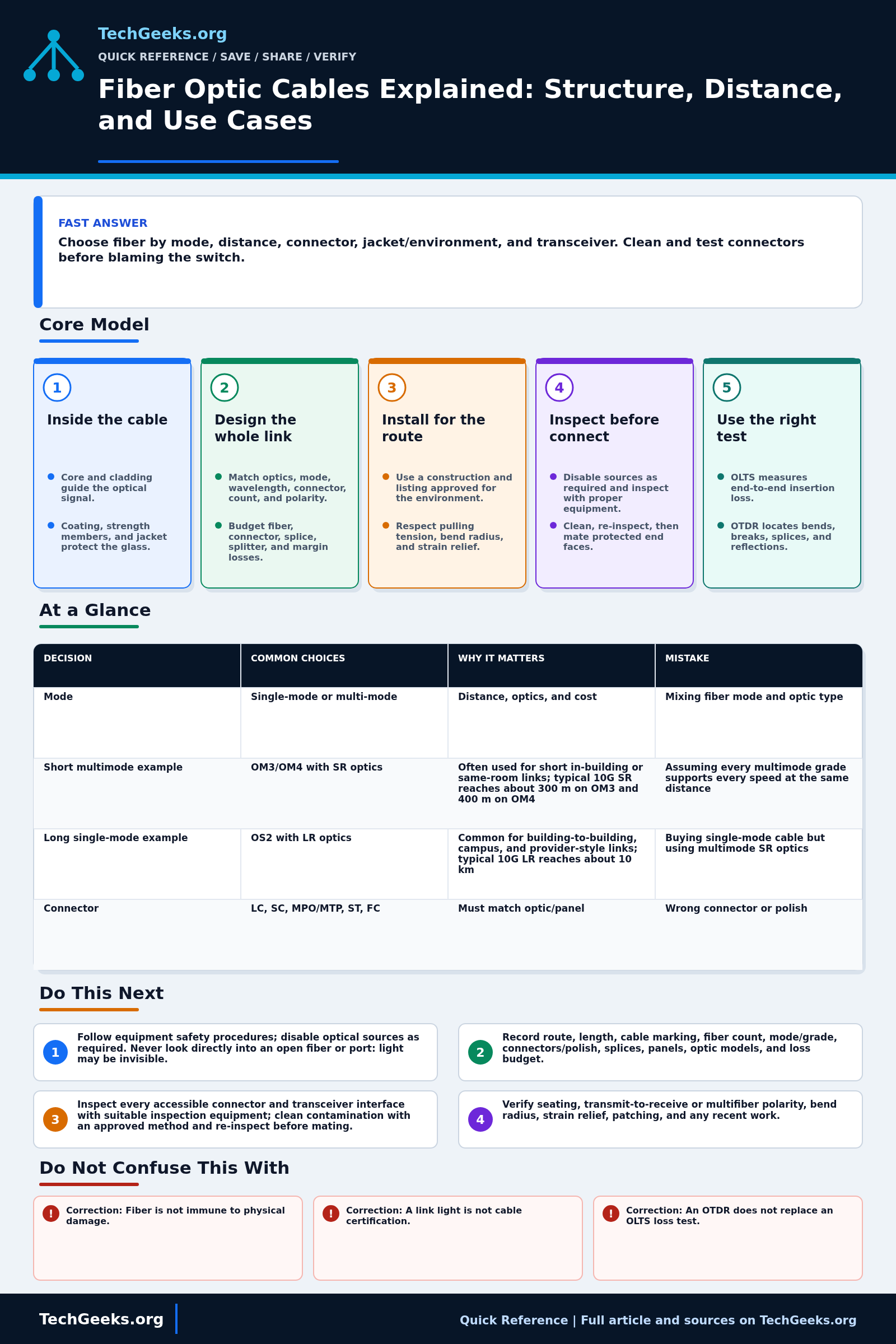
An optical fiber is a very thin glass waveguide. Light travels through its core and is guided by the surrounding cladding; protective coating, buffer, strength members, and an outer jacket turn that fragile glass into a usable cable. Those layers have different jobs, so the core carries the signal while the cable construction supplies handling strength, bend control, moisture protection, and the environmental or fire rating required for the installation.
A working network link is a system, not just a strand of glass. The transceivers must match the fiber mode and application, the connectors must match the ports and polish, and the installed length plus connector and splice losses must fit inside the optical budget. Duplex Ethernet commonly uses one strand to transmit in each direction, but single-fiber bidirectional and multifiber parallel applications are also common, so count and polarity must be documented.
Cleanliness and testing determine whether a correctly selected cable performs as designed. Inspect and clean both mating surfaces before connection, protect unused interfaces with clean caps, and avoid exceeding the cable manufacturer's pulling tension and bend radius. Use an optical loss test set (OLTS) to measure end-to-end loss and an optical time-domain reflectometer (OTDR) to locate bends, breaks, splices, or reflective events along the route.
The Fast Comparison
| Decision | Common choices | Why it matters | Mistake |
|---|---|---|---|
| Mode | Single-mode or multi-mode | Distance, optics, and cost | Mixing fiber mode and optic type |
| Short multimode example | OM3/OM4 with SR optics | Often used for short in-building or same-room links; typical 10G SR reaches about 300 m on OM3 and 400 m on OM4 | Assuming every multimode grade supports every speed at the same distance |
| Long single-mode example | OS2 with LR optics | Common for building-to-building, campus, and provider-style links; typical 10G LR reaches about 10 km | Buying single-mode cable but using multimode SR optics |
| Connector | LC, SC, MPO/MTP, ST, FC | Must match optic/panel | Wrong connector or polish |
| Jacket | Riser, plenum, outdoor, armored, LSZH | Safety and environment | Using indoor cable outdoors |
| Test | Visual fault locator (VFL), power meter, OTDR | Find faults and prove budget | Assuming link light means link quality |
Advanced Notes and Design Boundaries
Core size and an OM or OS label explain only part of a fiber channel. The usable design also depends on optic wavelength and power limits, modal bandwidth or dispersion, connector and splice loss, cable construction, route conditions, launch method, and the acceptance standard named for the project.
- Calculate two related budgets: the equipment optical-power budget from transmitter and receiver limits, and the cabling loss allowance from fiber attenuation, mated pairs, splices, splitters, and design margin. A path must satisfy receiver sensitivity without exceeding receiver overload.
- Insertion loss describes power removed from the forward signal, while reflectance and optical return loss describe returned power. Connector polish, contamination, air gaps, and poor end-face geometry can affect both, and low insertion loss alone does not characterize reflection-sensitive links.
- Macrobending and microbending loss depend on fiber design, bend geometry, wavelength, cable construction, and installation stress. A link that passes at one wavelength can reveal bend-related loss more strongly at another, so use the wavelengths and limits specified for the application and test standard.
- An OLTS or light-source-and-power-meter test is the primary end-to-end insertion-loss measurement. An OTDR resolves distributed loss and individual events from backscatter and reflection, but launch conditions, dead zones, event thresholds, launch and receive cords, fiber settings, and test direction affect interpretation.
- For multimode acceptance testing, use the launch condition required by the applicable standard, commonly an encircled-flux controlled source. For single-mode work, reference-cord quality and connector polish remain critical; preserve the test setup reference and record wavelength, method, limit, and direction with each result.
Troubleshooting Workflow
Preserve the loss evidence before moving patch leads or changing optics. Fiber faults often combine contamination, bend stress, and poor documentation, so each cleaning, route correction, or component substitution should be followed by the same referenced measurement.
- Make the link safe according to the equipment procedure, disable known optical sources where required, and never inspect an open fiber or port with the unaided eye because communications wavelengths may be invisible.
- Document the route, measured length, cable marking, fiber count, mode and grade, connectors and polish, splices, patch panels, transceiver applications, and expected loss budget.
- Inspect every accessible connector and transceiver interface with suitable inspection equipment; clean contamination with an approved method and re-inspect before mating.
- Verify seating, transmit-to-receive or multifiber polarity, bend radius, strain relief, patching, and any recent work. Use a VFL only within its rated distance and on a disconnected, compatible path to identify gross breaks or routing errors.
- Measure actual receive power at the operating wavelength or perform an OLTS end-to-end loss test with correctly referenced cords, then compare the result with the transceiver limits and calculated cabling allowance.
- If loss is excessive or intermittent, run an OTDR with the correct fiber type, wavelength, range, pulse settings, and launch and receive cords; correlate each event distance with route records, repair the physical cause, then repeat the end-to-end loss test.
Evidence and Acceptance Checks
The distance examples and test roles here are documentation-backed by standards catalogs, TIA material, IEC safety and inspection requirements, and independent FOA installation guidance. No cable was pulled, bent, contaminated, or measured by TechGeeks for this article. The 10G SR and LR examples are application examples, not measured guarantees for an unspecified optic or route.
- Design acceptance: the exact optic application supports the selected fiber grade and length, and the worst-case power and cabling-loss budgets include every connector, splice, splitter, and an explicit engineering margin.
- Pathway acceptance: the printed cable legend and manufacturer data satisfy indoor, riser, plenum, wet-location, outdoor, armor, pulling-tension, and bend requirements that apply to the route.
- Test acceptance: end-to-end insertion loss is measured at the specified wavelengths with the required reference and launch condition; OTDR traces supplement rather than replace that result.
- Operational acceptance: receive power remains between overload and sensitivity limits, link error counters stay stable under representative traffic, and as-built strand, polarity, route, and test records are retained.
Safety, Code, and Recovery Boundaries
Never view an open optical interface directly: hazardous energy can be invisible, and ordinary eyewear does not make inspection safe. Follow IEC 60825-2 equipment procedures and use a suitable video probe. Dispose of cleaved fiber safely. Building-entry, fire-stop, plenum, riser, bonding, and grounding rules vary by jurisdiction; metallic armor or messenger wire removes the assumption that an entire cable is dielectric. Route records may reveal physical security and service topology, so limit access where that matters.
Before changing an in-service route, save receive levels, error counters, patching photos, labels, and the original loss report. Keep an inspected known-good bypass or spare pair where availability justifies it. Roll back by restoring the original optics and patch map; if the original path no longer meets its recorded budget, stop service migration and repair or recertify the plant rather than accepting a link outside its recorded optical budget.
What This Does Not Mean
- Correction: Fiber is not immune to physical damage. It resists electromagnetic interference, but tight bends, crushing, excessive pulling, moisture entry, and dirty end faces can degrade or break a link.
- Correction: A link light is not cable certification. The link may operate with little margin, excessive errors, or intermittent loss and still show an up state.
- Correction: An OTDR does not replace an OLTS loss test. The tools answer different questions: total end-to-end insertion loss versus the location and character of events.
- Correction: Jacket color is an identification aid, not proof of mode, grade, fire rating, or outdoor suitability. Read the printed cable legend and product documentation.
The sources explain design and test practice; they do not certify the unknown cable in a wall, prove that an online product has the advertised glass or fire rating, or establish that every 10G optic reaches the examples in the table. An OTDR event map also cannot prove total channel compliance without the specified end-to-end loss test. Exact application and installation records remain controlling evidence.
Real-World Use Cases
- Use single-mode for long distance and future flexibility, especially between buildings, racks separated by unknown future speeds, and runs that are expensive to replace.
- Use multimode where existing infrastructure and short data center runs make sense, especially if the optics and patch panels are already standardized on OM3 or OM4.
- Treat distance examples as design starting points, then verify the exact optic standard and vendor data sheet before buying.
- Use rated cable for the space it passes through: plenum for plenum spaces, riser for vertical risers, outdoor or armored cable where moisture or physical damage is expected.
- Keep connectors capped and clean because one dirty end face can look like a bad transceiver.
Failure Patterns to Recognize
- Dirty end faces cause high loss.
- Sharp bends or crushed cable create attenuation.
- An optic/fiber-mode mismatch is unsupported unless the exact Ethernet application and vendor documentation explicitly permit both modes.
- Outdoor moisture damages indoor-rated cable.
Common Mistakes
- Touching fiber end faces.
- Pulling fiber like copper cable.
- Ignoring bend radius.
- Skipping cleaning before testing.
- Buying the cable before choosing the optics.
Quick Checklist
- Identify distance and environment.
- Choose single-mode or multimode.
- Match connectors to panels and optics.
- Check jacket rating.
- Verify the optic distance table for your speed and fiber grade.
- Clean and test before go-live.
Common Questions
Useful Gear And Buyer Notes
Affiliate disclosure: As an Amazon Associate, TechGeeks may earn from qualifying purchases. The product links below are buying references, not a requirement to buy a specific brand or seller. Verify compatibility, seller quality, warranty, and current specs before ordering.
Purchase only after the optic, route, and test plan are known. Marketplace titles often omit jacket listing, polish, actual fiber grade, wavelength support, and the limitations of low-cost meters or visual fault locators; confirm those details in the manufacturer data sheet and use calibrated instruments for acceptance work.
- Amazon search: LC single mode fiber patch cable
- Amazon search: fiber optic cleaning kit
- Amazon search: visual fault locator fiber
Related TechGeeks Reading
- 2.5GbE vs 10GbE for a Home Lab helps set the required network speed before an optical application is chosen.
- Networking Field Notes: Start Here links the wider series on physical links, switching, and diagnosis.
Distance and Test-Method Limits
The 10G SR and LR distances in the comparison are examples for specific optical applications, not universal fiber limits. Use the exact transceiver reach table and the required inspection, loss-test, and safety procedures. Cable listings and pathway requirements must match the actual route and local authority's rules.
References
- The Fiber Optic Association: Fiber Optic Cable
- The Fiber Optic Association: Bend Radius
- TIA: standards
- TIA: ANSI/TIA-568.3-E optical fiber cabling component standard announcement
- IEC 61300-3-35:2022 connector and transceiver end-face inspection
- IEC 60825-2:2021 optical fiber communication system safety
- Fluke Networks: Troubleshooting Fiber