LC vs SC vs ST vs FC vs MPO/MTP: Fiber Connectors Explained
 Tech Guru
Quick Answer
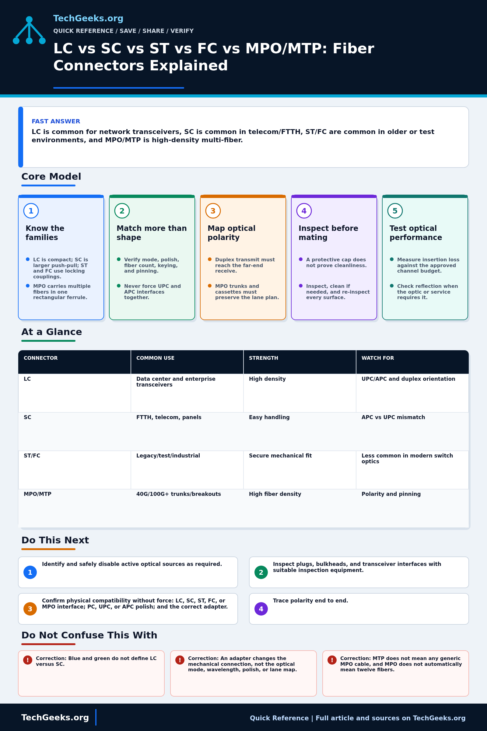
LC is common on compact Ethernet optics; SC on access networks and panels; ST and FC on legacy, industrial, or test paths; MPO/MTP on multifiber links. Choose only after checking both ports, fiber mode, polish, strand count, pinning, and polarity. Never force a connector or directly mate UPC to APC. A matching shape does not prove a usable optical link.
Start Here: The Beginner Foundation
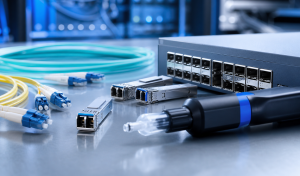
A fiber connector aligns one or more tiny glass cores so light can cross a removable joint. LC is a compact connector widely used on pluggable Ethernet optics, SC is a larger push-pull family common in panels and access networks, ST uses a bayonet coupling, and FC uses a threaded coupling. MPO is a rectangular multifiber interface used for dense trunks and parallel optics; MTP is US Conec's branded MPO connector family, not a separate generic interface name.
Connector shape is only the first match. The two sides must also have compatible fiber mode, ferrule polish, keying, guide-pin arrangement where applicable, fiber count, and optical polarity. UPC and APC end faces use different geometries and should not be directly mated; green and blue housings are common visual cues for APC and UPC, but markings and product documentation are stronger evidence than color.
Every connection adds some loss and reflection, and contamination can damage both mating surfaces. Keep protective caps clean, avoid touching ferrules, inspect each end face with suitable equipment, clean when needed, and re-inspect before mating. For duplex links, confirm transmit reaches receive; for MPO links, validate the documented polarity method and lane map across trunks, cassettes, adapters, and equipment ports.
The Fast Comparison
| Connector | Common use | Strength | Watch for |
|---|---|---|---|
| LC | Data center and enterprise transceivers | High density | UPC/APC and duplex orientation |
| SC | FTTH, telecom, panels | Easy handling | APC vs UPC mismatch |
| ST/FC | Legacy/test/industrial | Secure mechanical fit | Less common in modern switch optics |
| MPO/MTP | 40G/100G+ trunks/breakouts | High fiber density | Polarity and pinning |
Advanced Notes and Design Boundaries
Connector names identify mechanical interface families, not complete channel designs. A reliable specification also records ferrule polish, fiber grade, strand count, male or female guide-pin state for MPO, polarity method, wavelength, and the insertion-loss and reflectance limits required by the optic.
- LC commonly uses a 1.25 mm cylindrical ferrule, while SC, ST, and FC commonly use 2.5 mm cylindrical ferrules; this affects density and cleaning or inspection tooling but does not define fiber mode or polish by itself.
- UPC and APC control physical contact and reflection differently. APC is commonly an angled single-mode interface selected for stricter reflectance needs, while many Ethernet transceivers specify PC or UPC; never assume an APC patch lead is acceptable merely because the connector family fits.
- MPO channel design must specify fiber count and row layout, key orientation, pinned versus unpinned mating, polarity method, lane assignment, and whether the trunk is base-8, base-12, base-16, or another architecture. A correct-looking assembly can produce a complete lane-map failure.
- MTP is a registered US Conec brand of MPO-format connectivity with product-specific mechanical features. Procurement documents should state the standards interface and required performance rather than using MPO and MTP as unexplained interchangeable quality grades.
- IEC 61300-3-35 visual inspection classifies contamination and defects, but current guidance explicitly says inspection does not replace optical performance measurements. Acceptance criteria should include insertion loss and, where the application requires it, reflectance or optical return loss.
Troubleshooting Workflow
Work from the optical path rather than the connector color. Record the current lane map and measured power first, then substitute one inspected component at a time so a polarity error is not mistaken for contamination or a failed optic.
- Identify and safely disable active optical sources as required; record both equipment ports, adapter types, connector families, polish, fiber mode, fiber count, and the intended duplex or parallel optical application.
- Inspect plugs, bulkheads, and transceiver interfaces with suitable inspection equipment. Clean contaminated surfaces with the correct cylindrical- or rectangular-ferrule method, then re-inspect before any mating.
- Confirm physical compatibility without force: LC, SC, ST, FC, or MPO interface; PC, UPC, or APC polish; and the correct adapter. Replace cracked latches, damaged boots, loose adapters, or visibly damaged ferrules.
- Trace polarity end to end. For duplex links, map local transmit to remote receive; for MPO links, verify keying, pinning, fiber count, polarity method, cassette mapping, breakout labels, and transceiver lane assignment against the design.
- Measure receive power or insertion loss at the operating wavelength and compare each mated pair and the complete channel with the approved budget. Check return loss or reflectance when required by the optic or service.
- Change one element at a time using inspected known-good patch leads or adapters. If loss follows one connector, reterminate or replace it; if the location is uncertain, use an OTDR with suitable launch and receive cords, then repeat the end-to-end loss test after repair.
Evidence and Acceptance Checks
This comparison is documentation-backed. It was checked against current IEC connector-interface and end-face-inspection records, US Conec material for the MTP brand, and the independent Fiber Optic Association connector guide. TechGeeks did not assemble, inspect, or meter a sample LC, SC, ST, FC, or MPO channel for this draft, so no original insertion-loss, reflectance, durability, or interoperability result is claimed.
- Procurement acceptance: document compatible interfaces, polish, mode, and pinning at each mating pair, plus the fiber count and lane map across the complete path. A hybrid cord can have different connector families at its two ends; each end still has to match its own port.
- Installation acceptance: each accessible end face passes the applicable inspection rule after cleaning, with no UPC-to-APC mating or forced mechanical fit.
- Service acceptance: transmit reaches the intended receive lane and measured end-to-end loss fits the approved channel budget at the operating wavelength; reflectance is measured when the application requires it.
- Record the cable and cassette part numbers, polarity method, test instrument and reference method, wavelength, limits, results, and the identity of each strand or lane.
Safety, Recovery, and Installation Boundaries
Optical communications energy may be invisible. Do not look into a connector or transceiver, and follow the equipment isolation and inspection-tool procedures for the source class. Broken fiber scraps can penetrate skin and should be collected in a suitable container. Fire rating, pathway, and workplace requirements are installation-specific and belong to the authority having jurisdiction, not to a connector color chart. Connector choice has no direct privacy effect, but labeling can expose topology and circuit ownership, so protect operational records in shared facilities.
Before repatching, photograph and label both ends, save switch and optic status, and keep one inspected known-good cord of the exact required type. If the change fails, restore the original cord and lane order, confirm receive power and error counters, and stop if a ferrule is damaged or a valid loss budget cannot be recovered.
What This Does Not Mean
- Correction: Blue and green do not define LC versus SC. They commonly indicate UPC versus APC on single-mode products, while connector family is determined by the mechanical interface.
- Correction: An adapter changes the mechanical connection, not the optical mode, wavelength, polish, or lane map. A physically connected link can still be optically incompatible.
- Correction: MTP does not mean any generic MPO cable, and MPO does not automatically mean twelve fibers. Product brand, row layout, fiber count, pinning, and polarity must be specified.
- Correction: A dust cap does not guarantee a clean end face. Caps can carry contamination, so inspect before connection even when an interface was capped.
The cited interface standards establish dimensions and test methods; they do not prove that two marketplace listings meet those standards, that a visually clean connector meets the link budget, or that a particular MPO cassette maps lanes correctly. The FOA guide corroborates terminology but is not a certification record for any product. Only part-specific documentation and measurements on the installed channel answer those questions.
Real-World Use Cases
- Match connector to optic and patch panel.
- Check APC vs UPC before plugging green/blue connectors.
- Use duplex LC for common SFP links.
- Use MPO/MTP only with polarity and breakout plan documented.
Failure Patterns to Recognize
- APC and UPC are connected together and reflect/loss issues appear.
- MPO polarity is wrong.
- Simplex/duplex orientation is reversed.
- Dirty connectors create intermittent loss.
Common Mistakes
- Buying by connector picture only.
- Ignoring polish type.
- Touching ferrules.
- Using force when a connector does not fit.
- Failing to label fiber pairs.
Quick Checklist
- Identify optic connector.
- Identify panel connector.
- Check polish.
- Check fiber mode.
- Inspect both mating surfaces, clean if needed, and re-inspect before connecting.
- Measure received power and end-to-end loss against the channel budget.
Common Questions
Useful Gear And Buyer Notes
Affiliate disclosure: As an Amazon Associate, TechGeeks may earn from qualifying purchases. The product links below are buying references, not a requirement to buy a specific brand or seller. Verify compatibility, seller quality, warranty, and current specs before ordering.
Buy fiber components from the written channel specification, not from a connector photo. Search results can mix single-mode and multimode, UPC and APC, pinned and unpinned MPO, and incompatible polarity methods under nearly identical titles; verify the manufacturer part number before ordering.
- Amazon search: LC UPC fiber patch cable
- Amazon search: SC APC fiber patch cable
- Amazon search: MPO fiber cassette
Related TechGeeks Reading
- 2.5GbE vs 10GbE for a Home Lab helps decide the link speed and optic before selecting its fiber interfaces.
- Networking Field Notes: Start Here collects the broader deployment and troubleshooting series.
Standards and Product Limits
The references include SC, LC, MPO, and end-face inspection standards, plus US Conec's MTP documentation. They describe interfaces and test methods, not the quality of an unknown patch cord. Match the exact part numbers, polish, pinning, lane map, and loss budget for the channel you will install.
References
- The Fiber Optic Association: Fiber Optic Connector Identifier
- The Fiber Optic Association: Connector and polish terminology
- IEC 61754-20:2012+A1:2022: LC connector family interfaces
- IEC 61754-4:2022+A1:2026: SC connector family interfaces
- IEC 61754-7-1:2014: one-row MPO connector family
- IEC 61754-7-2:2017: two-row MPO connector family
- IEC 61300-3-35:2022: connector and transceiver end-face inspection
- US Conec: MTP PRO connector polarity solutions