PoE vs PoE+ vs PoE++: Why Cameras and APs Reboot
 Tech Guru
Quick Answer
When a camera or access point reboots under load, compare its required PoE type and class with the port limit, total switch budget, and installed cable. Source watts and power available at the device differ. Use authorized access to a standards-based switch or injector, save the working port settings, and plan a brief endpoint outage before substituting a cable or power source.
Start Here: The Beginner Foundation
Power over Ethernet carries DC power and Ethernet data over the same balanced twisted-pair channel. The power sourcing equipment, or PSE, is usually a switch or injector; the powered device, or PD, may be a phone, camera, access point, controller, or sensor. In standards-based IEEE PoE, the PSE first detects a valid PD signature and then classifies or negotiates power before applying normal operating power. Passive PoE is a different product behavior that may place voltage on conductors without IEEE detection, so its voltage, pin use, polarity, and device compatibility must never be assumed from the word PoE alone.
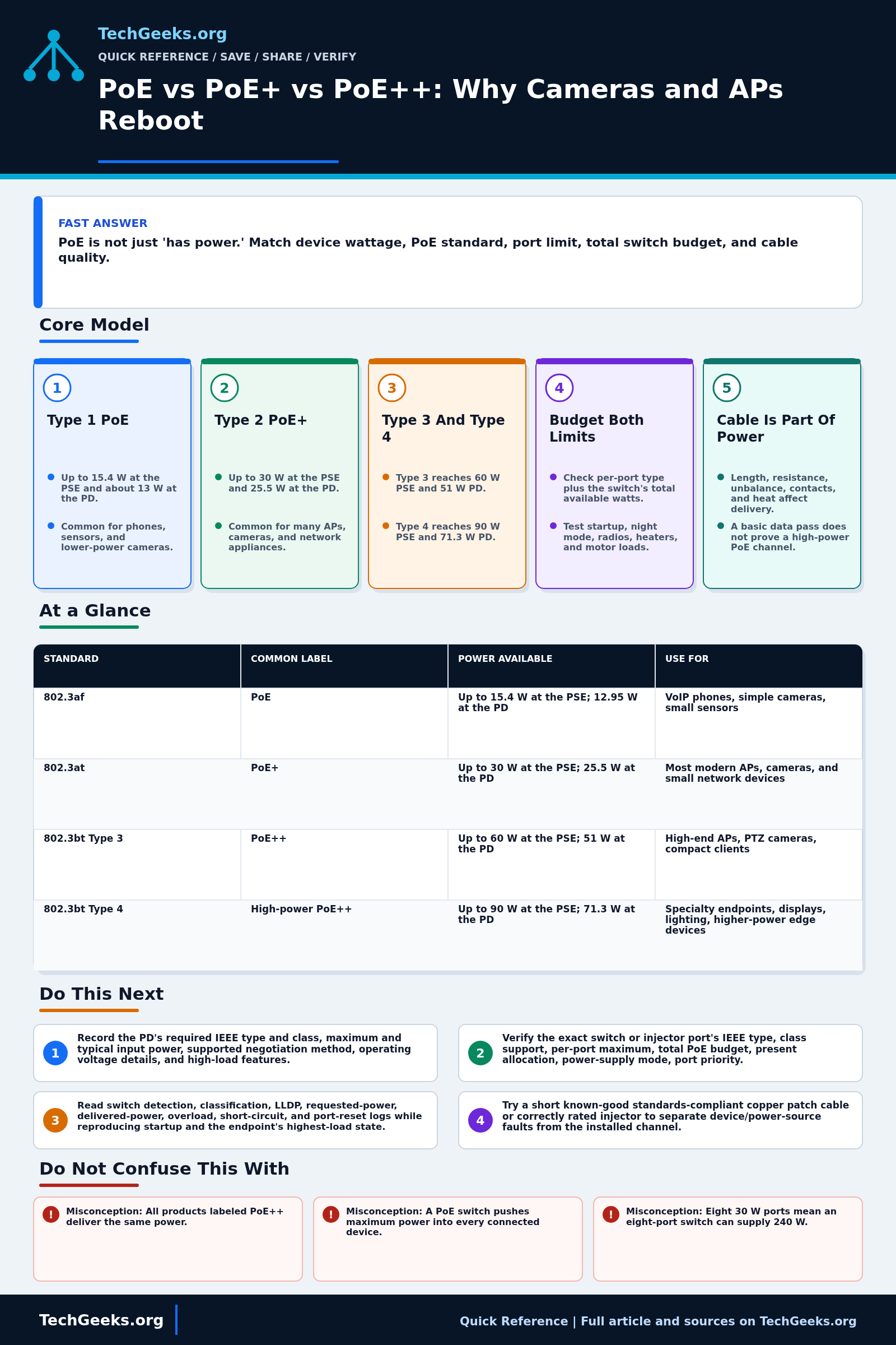
The IEEE types define both power at the source and a lower amount guaranteed at the device after allowed cable loss. Type 1, commonly called PoE or associated with 802.3af, supplies up to 15.4 W at the PSE and about 13 W at the PD. Type 2, PoE+ or 802.3at, raises that to 30 W and 25.5 W. IEEE 802.3bt adds Type 3 with up to 60 W at the PSE and 51 W at the PD, and Type 4 with up to 90 W at the PSE and 71.3 W at the PD. Marketing terms such as PoE++ are not precise enough by themselves; verify the IEEE type, class, and guaranteed PD power in both data sheets.
A working design must satisfy the per-port capability, the switch's total PoE budget, and the endpoint's maximum demand at the same time. A switch may have many PoE-capable ports but insufficient watts to run all of them at their highest class. Device draw can rise when an AP enables more radios, a camera turns on infrared lighting or a heater, or a motor moves. Cable length, conductor resistance, pair balance, connector quality, temperature, and bundles affect loss and heat. Plan measured headroom based on the load profile and failure policy rather than treating any single percentage as an IEEE requirement.
The Fast Comparison
| Standard | Common label | Power available | Use for | Watch for |
|---|---|---|---|---|
| 802.3af | PoE | Up to 15.4 W at the PSE; 12.95 W at the PD | VoIP phones, simple cameras, small sensors | Not enough for many Wi-Fi 6/6E/7 APs or IR/PTZ cameras |
| 802.3at | PoE+ | Up to 30 W at the PSE; 25.5 W at the PD | Most modern APs, cameras, and small network devices | Total switch budget can still run out |
| 802.3bt Type 3 | PoE++ | Up to 60 W at the PSE; 51 W at the PD | High-end APs, PTZ cameras, compact clients | Requires bt-capable switch/injector and suitable cabling |
| 802.3bt Type 4 | High-power PoE++ | Up to 90 W at the PSE; 71.3 W at the PD | Specialty endpoints, displays, lighting, higher-power edge devices | Listings that claim 100 W may use proprietary behavior |
Advanced Notes and Design Boundaries
The wattage label is only the start of a PoE design. Allocation behavior, pair use, Link Layer Discovery Protocol (LLDP), power-supply redundancy, cable resistance, connector condition, ambient temperature, and the endpoint's peak operating state determine whether power remains stable.
- Keep source and load numbers distinct: Type 1 is 15.4 W PSE and about 13 W PD, Type 2 is 30 W and 25.5 W, Type 3 reaches 60 W and 51 W, and Type 4 reaches 90 W and 71.3 W. A vendor's proprietary 95 W or 100 W label is not the standardized Type 4 PSE value.
- Classification reserves power according to the PD and PSE capabilities; optional data-layer negotiation such as LLDP can refine allocation on supporting equipment. Compare requested, allocated, and measured power in switch telemetry instead of equating current draw with class.
- IEEE 802.3bt Type 3 spans lower and higher classes, and higher-power operation uses both pairsets. Type 3 and Type 4 equipment can use single-signature or dual-signature PD architectures, which affects classification and troubleshooting details.
- For high-power PoE, inspect DC loop resistance, pair-to-pair resistance unbalance, conductor gauge, connector contact quality, bundle size, and ambient temperature. Passing a basic data test does not establish acceptable power delivery or bundle heating.
- Define overload behavior before deployment. Managed PSEs may deny a new PD, cap its class, or shed lower-priority ports when the budget or power supply is constrained; UPS runtime and redundant-power configuration can change the available budget during an outage.
Troubleshooting Workflow
Capture the switch's port-power state before reproducing the reboot, then change only one layer: PD features, port, injector, patch lead, or installed channel. Correlating endpoint uptime with PSE detection, class, allocation, draw, and overload events prevents a short known-good cable from being mistaken for a permanent repair.
- Record the PD's required IEEE type and class, maximum and typical input power, supported negotiation method, operating voltage details, and high-load features such as radios, heaters, IR, motors, or USB output.
- Verify the exact switch or injector port's IEEE type, class support, per-port maximum, total PoE budget, present allocation, power-supply mode, port priority, and any budget reduction on UPS or redundant power.
- Read switch detection, classification, LLDP, requested-power, delivered-power, overload, short-circuit, and port-reset logs while reproducing startup and the endpoint's highest-load state.
- Substitute a short known-good standards-compliant copper patch cable or a known-good correctly rated injector to separate PD or PSE behavior from the installed channel.
- Wire-map and certify the full installed link, then evaluate length, DC resistance and unbalance where supported, connectors, patch cords, conductor material, bundle temperature, and any midspan connections.
- Correct the failed layer, rerun cold start and sustained peak-load tests, confirm budget with all expected PDs active, and document measured draw plus deliberate capacity and failure headroom.
Evidence and Acceptance Tests
Evidence status: documentation-backed. TechGeeks reviewed IEEE-aligned Ethernet Alliance material, current cabling guidance, and independent Fluke Networks explanations; no original PSE, PD, cable-loss, or thermal lab was performed for this draft.
- Record the switch, power-supply, firmware, port, PD, cable route, negotiated class, requested and allocated watts, measured draw, and UTC timestamps.
- Cold-start the endpoint, enable its highest expected load, and run it with every planned PD active long enough to catch priority shedding or thermal behavior.
- Accept the design only when the device stays online, the port logs no power denial or overload, allocation remains inside both the port and total budget, and the installed channel passes the required cabling tests.
- Test the intended UPS or redundant-power failure state because a switch may expose fewer PoE watts after losing one supply.
- Restore the original port, injector, or cable and confirm service if the candidate change fails any acceptance condition.
Electrical, Privacy, and Recovery Boundaries
- Do not connect passive or proprietary power to an endpoint unless voltage, polarity, pair use, and product compatibility are explicitly documented; an RJ45 plug does not make the power mode safe.
- Use listed cable, connectors, pathways, and installation practices suitable for the environment, bundle, and local electrical/fire rules. Escalate damaged, hot, wet, outdoor, or building-to-building runs to a qualified cabling professional.
- Switch telemetry can identify device models, locations, schedules, camera activity, and outage times. Limit exports to authorized troubleshooting and redact site or client identifiers before sharing.
- Keep management access independent of the powered endpoint being tested, save the known-good configuration, and pre-stage a compatible injector or power supply when the device is operationally critical.
What This Does Not Mean
- A PoE++ label does not prove a specific IEEE type, class, guaranteed PD wattage, or compatibility with a proprietary high-power mode.
- A switch-reported current draw does not prove voltage and power margin at the endpoint after cable loss, nor does it show connector or bundle temperature.
- A passing Ethernet data test does not prove acceptable DC resistance, pair-to-pair unbalance, contacts, conductor material, or high-power thermal performance.
- One successful short-cable test can isolate the installed channel, but it does not prove the original switch and endpoint will remain stable when all production PDs reach peak demand.
Real-World Use Cases
- Illustrative arithmetic, not a measured installation: two APs drawing 18 W each, four cameras drawing 8 W each, and one controller drawing 12 W total 80 W at the devices. Port count alone does not establish the required source budget.
- Size the source budget from class allocation, cable loss, simultaneous peak loads, and the intended power-supply failure state. The hypothetical 80 W device total does not by itself establish an adequate switch rating.
- Leave headroom for startup, IR LEDs at night, radio power changes, future devices, and inaccurate product listings.
- Use quality copper cabling and avoid copper-clad aluminum for PoE runs.
- Check LLDP/CDP power negotiation on managed switches when a device requests less power than it needs.
Failure Patterns to Recognize
- AP reboots when radios go active.
- Camera works by day but fails when IR LEDs turn on.
- Switch logs power denied or overload.
- Long or poor cable run causes voltage drop or link issues.
Common Mistakes
- Buying an 8-port PoE switch with a tiny total power budget.
- Mixing passive PoE with standards-based PoE carelessly.
- Ignoring cable quality and bundle heat.
- Assuming every port can deliver the maximum at the same time.
Quick Checklist
- Check device power requirement and whether it is maximum, typical, or idle draw.
- Check port standard.
- Calculate startup, worst-case, temperature, redundancy, and growth margin from the actual design instead of applying one universal percentage.
- Review switch logs for denied power, overload, or class negotiation messages.
- Test with a shorter known-good cable.
- Leave documented growth headroom.
Common Questions
Useful Gear And Buyer Notes
Affiliate disclosure: As an Amazon Associate, TechGeeks may earn from qualifying purchases. The product links below are buying references, not a requirement to buy a specific brand or seller. Verify compatibility, seller quality, warranty, and current specs before ordering.
Choose a switch or injector only after matching the PD's IEEE type and maximum input, required data rate, port allocation, total budget under supply failure, and management telemetry. A tester used for high-power troubleshooting should report the measurements the installed-cabling standard and failure hypothesis actually require.
Related TechGeeks Reading
- My Ubiquiti UniFi Home Network: Business-Grade Networking at Home
- What Should Happen to Your Homelab During a Power Outage?
- Networking Field Notes: Start Here
References
- IEEE 802.3 Ethernet standards
- Ethernet Alliance: Innovation of IEEE 802.3 PoE
- Ethernet Alliance PoE Certification Program
- Fluke Networks: PoE negotiation and classification
- Fluke Networks: DC resistance unbalance for 802.3bt
- TIA Announcement: ANSI/TIA-568.2-E Balanced Twisted-Pair Cabling
- UL Solutions ICT Power Cable Certification Program