Where Should You Put Your Wi-Fi Access Points?
 Tech Guru
Quick Answer
Place access points near the rooms and seats that need reliable service, with the mounting orientation their antennas were designed for and a practical Ethernet/PoE route. Avoid metal cabinets and dense obstructions. Test a temporary location at its intended height with the weakest important client before drilling or buying more APs. Use local throughput, signal quality, busy-hour contention, and roaming results to choose the layout; neither signal bars nor a fixed AP count proves coverage.
The Reader Question
Why is my mesh or access point still slow in some rooms?
This guide is for home and small-office operators choosing locations before drilling holes or buying more radios. You need a floor plan, client and room priorities, wall/construction notes, an Ethernet/PoE plan, and at least one representative weak client. The goal is dependable coverage and capacity where work happens, with placement that can still be adjusted after validation.
Before You Start: Safe Defaults
- Use the mounting plane and orientation in the model's installation guide; ceiling, wall, in-wall, and directional antennas have different patterns.
- Avoid placing APs behind TVs, inside cabinets, beside metal racks, above hot equipment, or behind dense masonry.
- Prefer powered Ethernet (PoE) and wired backhaul for fixed APs; confirm switch power budget, cable category, link speed, and grounding/surge requirements.
- Temporarily mount or place APs at the proposed height before making permanent penetrations.
- Design for the weakest important client, 5/6 GHz requirements, room capacity, and roaming rather than the strongest laptop beside the AP.
- Export the existing channel/power settings and keep the old AP online until the new layout passes.
Reference Model
The model below starts with people and applications, then obstacles, cable routes, mounting pattern, RF plan, and validation. Open each step and annotate the floor plan with a requirement and measured result; a predicted heat map is not a post-installation survey.
Decision Matrix
| Choice | Best Fit | Watch Point |
|---|---|---|
| One router/AP | Small open space | Closets, brick, and multi-floor layouts break it quickly. |
| Multiple wired APs | Buildings whose measured coverage or capacity requires more than one cell | Needs cable runs and channel planning. |
| Wireless mesh | Rentals or no-cable constraints | Backhaul consumes airtime and placement still matters. |
| Outdoor AP | Patio, yard, camera, or detached workspace | Needs weatherproof cable, surge, and mounting care. |
Bad Hiding Places
Metal, reinforced concrete, masonry, low cabinets, mirrors, elevator shafts, appliances, water-heavy spaces, and AV racks can attenuate or reflect radio-frequency (RF) energy. A client may still show bars from 2.4 GHz while 5 or 6 GHz is weak, or it may hear the AP better than its low-power transmitter can reply. Measure both client experience and AP-reported uplink signal instead of inferring performance from an icon.
Multi-Floor Layouts
RF travels through floors as well as walls. Do not automatically stack APs directly above one another; model adjacent-floor coverage and stagger locations when that reduces same-channel contention while serving high-use areas. However, there is no universal one-AP-per-floor or spacing rule. Concrete slabs, radiant barriers, open stairwells, atria, antenna patterns, transmit power, and client density can reverse the recommendation.
Coverage, Capacity, and Roaming Criteria
Define the application first. A stationary sensor may tolerate low throughput and weak signal; a voice call needs consistent signal-to-noise ratio (SNR), low loss, and overlap that lets the client roam before the old cell fails. Cisco Meraki documents a classic voice-oriented starting point around -67 dBm and 25 dB SNR, while Aruba's current design guide describes roughly -55 to -65 dBm targets depending on modulation and capacity. These are design examples, not guarantees: use the requirements of the actual clients and applications.
More APs can add capacity by creating smaller cells and more channel reuse, but only with a workable channel and power plan. Too many high-power radios on the same channel increase contention. Start with 20 or 40 MHz channels in busy multi-AP environments unless wider channels have a measured benefit and enough clean spectrum. On 2.4 GHz, avoid creating many overlapping 40 MHz cells.
Validation After Mounting
After the radios have settled on channels and power, walk a fixed route with the weakest important phone, scanner, camera, or laptop in its normal orientation. Check RSSI, SNR/noise, channel, channel utilization, retries where available, LAN throughput, latency under load, roaming interruption, and AP association. Repeat at busy and quiet times.
- Test video-call seats, desks, conference spaces, TVs, cameras, doorbells, and outdoor work areas, not only hallways.
- Use a local wired test server to separate Wi-Fi capacity from ISP and SaaS variability.
- Review per-band client signal, SNR, retries, channel utilization, neighboring APs, channel width, and wired uplink negotiation.
- For roaming, maintain a call or continuous low-rate test while walking the same route and record the AP transition and interruption.
- Adjust one variable at a time: location first, then channel/power/width. Lowering AP power alone does not force every client to roam.
A Practical Pilot Scenario
Draw the floor plan and mark high-use seats, client counts, existing cable, wall/slab types, outdoor boundaries, and complaints. Move one AP temporarily to the proposed height and orientation, connect wired backhaul, and test the same fixed points before and after. For a mesh-only layout, measure the node's backhaul as well as its client-facing signal; placing a node inside the dead zone usually gives it a poor upstream path.
The pilot passes when priority points meet the declared application targets, the weakest client can transmit reliably, wired/mesh backhaul is not the bottleneck, roaming interruption is acceptable, and neighboring APs do not create excessive same-channel contention. If one AP cannot satisfy both coverage and capacity, add a wired cell near demand rather than turning every radio to maximum.
Implementation Details
Plan cable and power before committing to radio locations. A perfect prediction with no safe Ethernet route is not deployable, while an easy cable route inside a metal closet is not an RF design. Use temporary mounts and service loops until measured results justify final termination.
- Draw the floor plan; mark application requirements, client density, weak-client types, complaints, outdoor limits, and floor-to-floor relationships.
- Identify construction materials, interference candidates, existing AP neighbors, safe cable paths, and PoE/switch capacity.
- Choose the antenna pattern and model for the mounting plane, environmental rating, regulatory domain, and expected client bands.
- Temporarily mount at the intended height/orientation and connect a verified Ethernet backhaul.
- Build a per-band channel, channel-width, and power plan; let automatic RF management settle before judging it.
- Run a predictive survey if available, then perform passive/active validation with representative clients at fixed points and along roaming paths.
- Move the AP before adding power when an obstruction or antenna pattern is the problem.
- Finalize the mount and cable only after the before/after results meet the written acceptance criteria.
Evidence and Testing Method
- Status: documentation-backed. TechGeeks reviewed current Aruba and Cisco Meraki RF design/site-survey guidance plus independent Clear To Send placement methodology. No original on-site RF survey or AP comparison was performed for this draft.
- Record floor plan revision, AP model/firmware, antenna orientation/height, country, channel/width/power, wired link, client model/driver, date/time, and occupancy.
- Use the same locations, device orientation, local test server, payload, and walk route before and after.
- Capture RSSI, SNR/noise, channel utilization, retries where available, LAN throughput, unloaded/loaded latency, roaming interruption, AP association, and backhaul metrics.
- Keep raw point measurements and note dead zones; a smoothed heat map can hide a small but important room or doorway.
Safety, Privacy, and Recovery Boundaries
Follow local electrical, low-voltage, firestop, plenum, landlord, structural, lightning, grounding, and outdoor-weatherproofing rules. Do not drill until hidden utilities are checked. Use listed PoE equipment and the vendor's indoor/outdoor rating. Outdoor Ethernet can introduce surge risk; involve a qualified installer where local code or the building requires it.
Survey files reveal floor plans, device names, AP locations, neighboring networks, and occupancy patterns. Limit sharing and retention, and do not collect client identifiers beyond the test need. Recovery is straightforward when changes are staged: restore the exported channel/power configuration, reconnect the old AP or cable, and remove the temporary mount. Keep at least one management path that does not depend on the AP being moved.
Validation Checklist
- Every high-use area has acceptable signal and latency.
- Clients roam between APs without long call drops.
- APs use non-overlapping channels where possible.
- Wireless backhaul is avoided or documented as a constraint.
- Outdoor coverage does not require opening interior AP power to maximum.
Maintenance Cadence
- After one week: review client distributions, channel utilization, retries, roam complaints, mesh backhaul, and AP power/channel changes.
- Monthly: inspect uplink negotiation, PoE budget, AP health, persistent weak clients, interference, and high-utilization cells.
- Quarterly or after furniture/construction changes: repeat the fixed-point and roaming route survey.
- After firmware, AP, client, or regulatory changes: revalidate band availability, channel plan, power, security, and priority applications.
Troubleshooting
| Symptom | Likely Cause | First Check |
|---|---|---|
| Strong bars but poor speed | Congestion, channel width, or bad backhaul | Check channel utilization and wired uplink speed. |
| Client sticks to far AP | Client roaming behavior, uneven cell coverage, or radio settings | Inspect client/AP association, overlap, channel, and power along the same walk route. Change one setting and retest; lower AP power does not guarantee a roam. |
| One room always weak | Wall material or AP placement problem | Move AP closer or add wired AP on the correct side of obstruction. |
Common Mistakes
- Putting the only AP in a wiring closet.
- Buying Wi-Fi 7 before fixing AP location and backhaul.
- Ignoring the exact AP antenna pattern and approved mounting orientation, or hiding it behind furniture.
- Adding mesh nodes in weak-signal locations where backhaul is already poor.
- Using speed tests beside the AP as proof that the far room is fixed.
Useful Gear And Buyer Notes
Choose an AP only after the floor plan establishes mounting plane, bands, client density, environmental rating, and PoE/uplink needs. Confirm the exact model's antenna pattern, regulatory approvals, power draw, mounting kit, firmware support, and return policy; the newest radio cannot compensate for the wrong location.
Affiliate disclosure: As an Amazon Associate, TechGeeks may earn from qualifying purchases. The product links below are buying references, not a requirement to buy a specific brand or seller. Verify compatibility, seller quality, warranty, and current specs before ordering.
- Amazon search: UniFi U7 Pro
- Amazon search: UniFi U7 Pro Max
- Amazon search: PoE switch 2.5GbE
- Amazon search: Cat6 cable 1000ft
- Amazon search: WiFi analyzer
Related TechGeeks Reading
- Networking Field Notes: Start Here
- My Ubiquiti UniFi Home Network: Business-Grade Networking at Home
- Homelab VLAN Design: Simple Network Segmentation That Works
What This Evidence Does Not Prove
Vendor design targets and a predictive model do not prove coverage in your construction, and one phone's RSSI does not represent every camera, scanner, laptop, or IoT radio. A strong downlink does not prove the client can transmit back, and a fast test beside the AP says nothing about roaming or busy-hour airtime.
This article does not calculate a universal AP count or spacing. Capacity depends on applications, simultaneous clients, channel reuse, regulatory domain, interference, and wired backhaul. Wi-Fi 7 features cannot repair an obstructed location or a congested channel plan.
Practical FAQ
Should APs go in the ceiling?
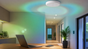
Ceiling APs generally work best when ceiling mounted in open areas. Wall and in-wall APs are better for rooms where the mounting plane matches the antenna design.
Is mesh bad?
No, but it is a compromise. Wired backhaul is more predictable when you can run it.
How many APs do I need?
Enough to cover high-use areas on 5/6 GHz at reasonable power, not enough to blanket every corner with maximum signal.
References
- Aruba ESP Campus Design: AP placement and 5/6 GHz coverage criteria
- Cisco Meraki: conducting Wi-Fi site surveys
- Cisco Meraki: channel planning and overlapping cells
- Cisco Meraki: high-density survey and placement guidance
- Clear To Send: independent placement, attenuation, power, and capacity design discussion
- IEEE 802.11 working group
Final Thought
The best Wi-Fi upgrade is often a ladder, a cable run, and a better AP location. Buy radios after the placement problem is visible.